

The Heart of Precision in Modern Automation
What is a Servo Motor?
A servo motor is a motor designed for precise position, speed, and torque control. Unlike conventional motors, it operates as a closed-loop control system, which includes:The motor itself,A feedback device (usually an encoder),A servo driver/controller.
The core advantage of a servo system lies in its feedback and correction mechanism. It continuously compares actual motion (via encoder signals) with target commands and corrects deviations instantly. This ensures extreme accuracy, making it indispensable in industries where precision is non-negotiable.
Servo Motor Definition: A servo motor is an actuator that faithfully “follows” command signals to execute precise motion control.
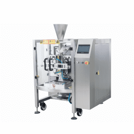
Is Your Packaging Machine Exhibiting These Control-Related Faults?
Problem 1: Inconsistent Bag Length & Inaccurate Seal/Cut Positions
- Our servo motors are equipped with 2500 PPR (Pulses Per Revolution) or higher resolution encoders, providing extremely fine position feedback.
- The matched servo drive features advanced algorithms that can execute complex motion profiles with sub-millisecond response times, ensuring the film pulling belts or sealing jaws stop at the exact commanded position, cycle after cycle.
Problem 2: Frequent “Deviation Counter Overflow” Alarms
- Our AC servo motors deliver high peak torque (up to 3x rated torque) to handle the demanding acceleration and deceleration of film pulling and sealing jaw mechanisms.
- The servo drives feature intelligent auto-tuning functions that automatically measure the load inertia and optimize the control loop gains. This ensures the motor can follow commands precisely without lagging, even under dynamic load changes.
Problem 3: Excessive Vibration and Noise During Operation
- We provide perfectly matched motor and drive pairs that are factory-tuned for smooth, quiet operation.
- The drives include adaptive notch filters that can automatically detect and suppress mechanical resonance frequencies, eliminating vibration and noise at the source.
Problem 4: Motor Overheating and Premature Failure
- We assist you in correctly sizing the servo motor based on a thorough analysis of your application’s torque, speed, and inertia requirements, ensuring the motor operates within its continuous duty zone.
- Our motors are designed with high-grade insulation (Class B or higher) and optimized cooling fins to ensure excellent thermal dissipation and a long, reliable service life.
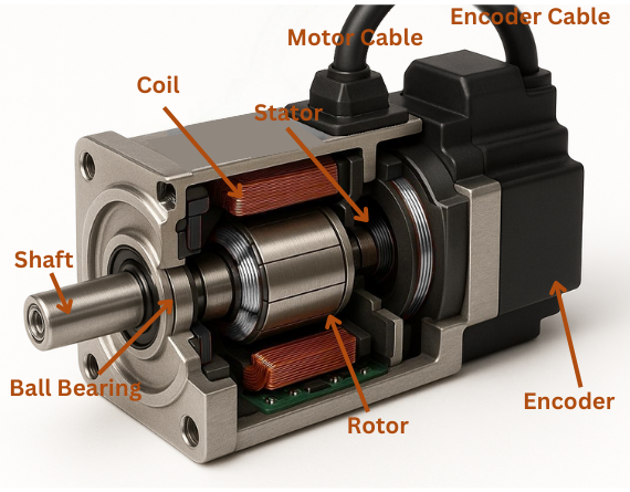
Servo Motor Working Principle
The working principle of a servo motor is based on closed-loop feedback control:
- Command Input: A PLC or motion controller sends position, speed, or torque commands to the driver.
- Comparison: The servo driver compares these signals with real-time encoder feedback.
- Power Amplification: Based on deviations, the driver adjusts voltage and current to the coils.
- Motor Rotation: The motor generates torque and rotates the shaft.
- Feedback Correction: The encoder detects actual motion and sends data back.
- Continuous Adjustment: The cycle repeats until the motor reaches the exact target point.
(See our servo motor diagram for a visual explanation.)
This constant cycle ensures the motor maintains accuracy even under disturbances such as load changes.
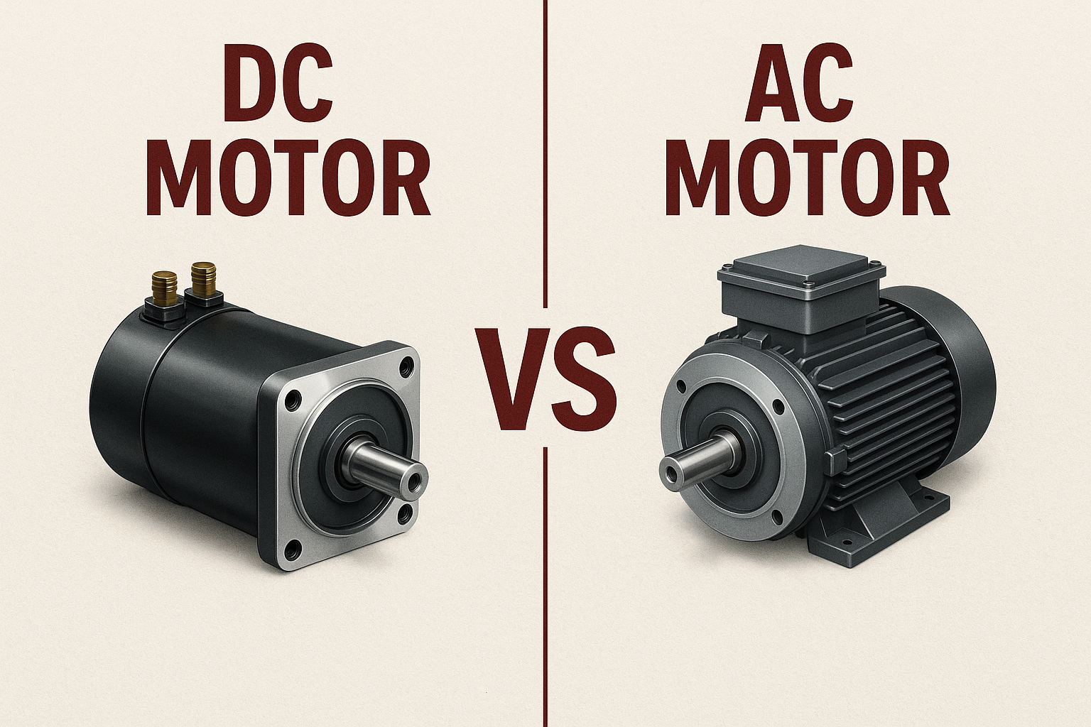
AC Servo Motor vs DC Servo Motor
Servo motors can be classified as:
DC Servo Motor – Simple design, easier control, historically common in low-power systems.
AC Servo Motor – Dominant in modern industry, especially Permanent Magnet Synchronous Motors (PMSM). They deliver higher efficiency, greater torque density, wider speed range, and low maintenance.
Answering key question: Is a servo motor AC or DC?
Both exist, but in industrial automation, AC servo motors are the standard choice.
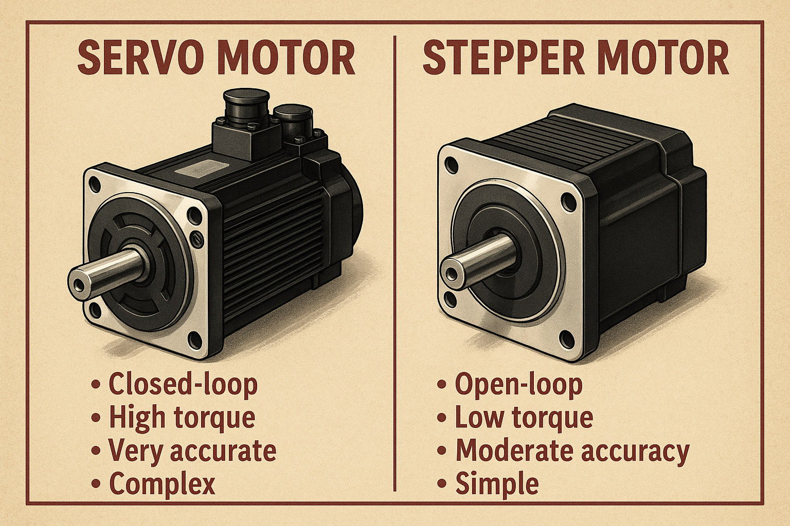
Servo Motor vs Regular Motor (Step Motor Example)
| Feature | Servo Motor | Stepper Motor (Regular Motor Example) |
|---|---|---|
| Control | Closed-loop with encoder feedback | Open-loop, no feedback |
| Precision | Extremely high | Moderate, risk of step loss |
| Overload Capacity | Strong, handles peak torque | Weak, stalls under overload |
| Speed Performance | Excellent, high-speed stability | Loses torque at high speed |
| Smoothness | Very smooth at low speeds | Vibration at low speed |
| Response | Fast and dynamic | Slower, delayed start/stop |
| Cost | Higher | Lower |
What is the difference between a servo motor and a regular motor?
In short: Servo motors are feedback-driven, precise, and powerful, while regular motors are simpler but less accurate.
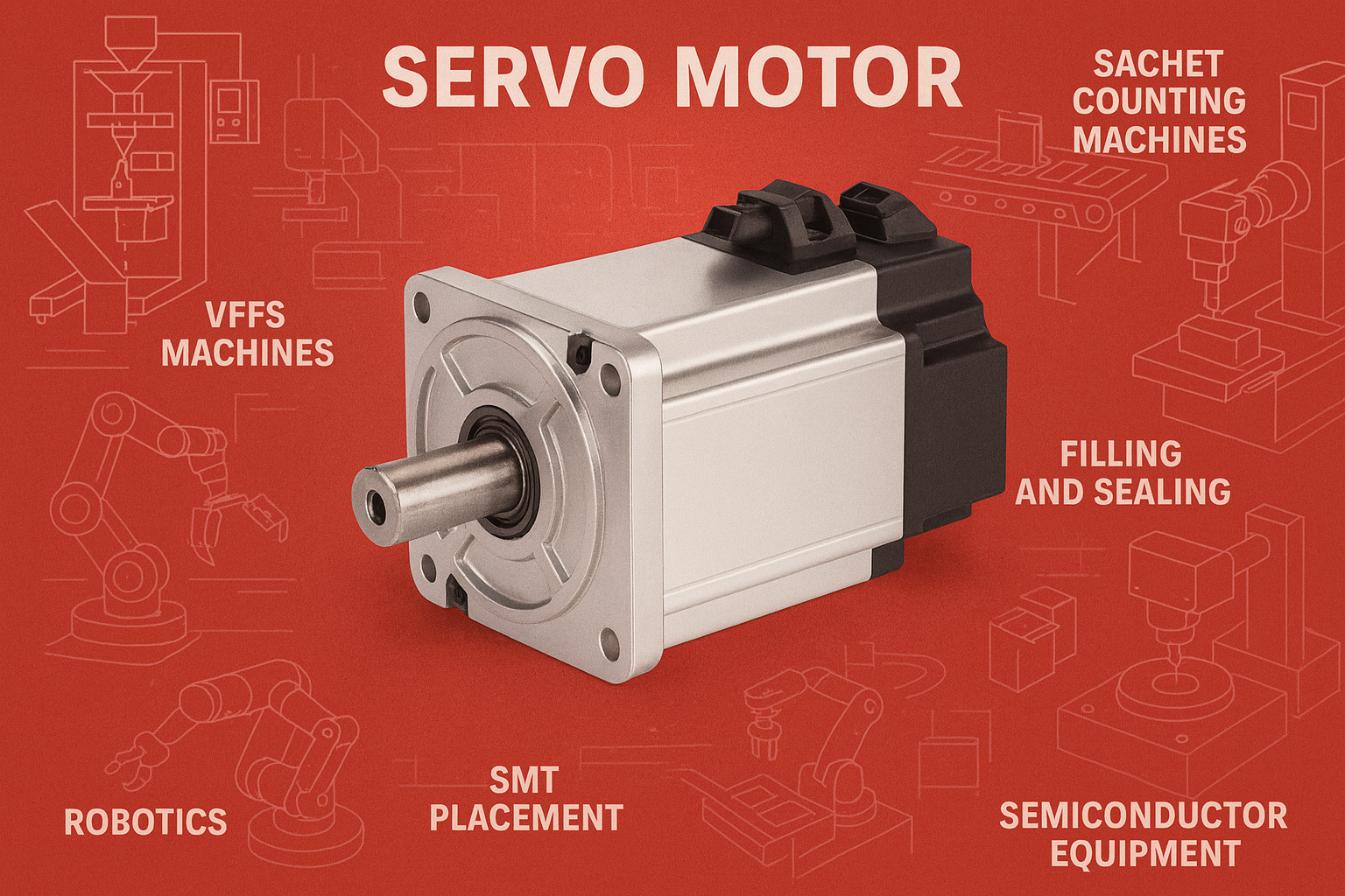
Application-Specific Selection Guide for Packaging Machinery
Application Axis | Key Requirement | Recommended Servo Feature |
VFFS Film Pulling | Precise, repeatable bag length; High acceleration/deceleration. | High-resolution encoder; High peak torque; Inertia matching. |
HFFS Film Feed / Infeed | Synchronized motion with product conveyor. | Electronic gearing/camming functions in the drive. |
Sealing Jaw Actuation | High torque for sealing pressure; Fast, precise open/close. | High peak torque; Brake option for vertical jaws. |
Auger/Volumetric Filler | Precise rotational angle for accurate dosing. | Absolute encoder for position memory after power loss. |
Unwind/Rewind Stand | Constant film tension control. | Torque control mode in the servo drive. |
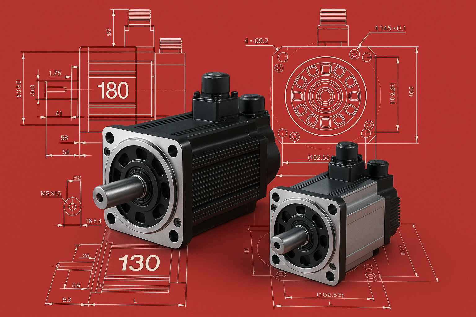
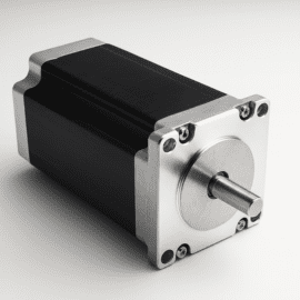
Servo Motor Specifications (130 & 180 Series Highlights)
130 Series (Medium Torque, High Precision)
- Power Range: 1.5 – 3.9 kW
- Rated Torque: 5 – 15 N.m
- Rated Speed: 1500 – 3000 r/min
- Ideal For: CNC equipment, automation lines
180 Series (Heavy-Duty, High Power)
- Power Range: 2.7 – 7.5 kW
- Rated Torque: 17 – 48 N.m
- Rated Speed: 1000 – 2000 r/min
- Ideal For: Large machine tools, heavy robotic arms, industrial equipment
General Specifications:
- Insulation Class: B (130°C)
- Protection Class: IP65
- Encoder: 2500 PPR Incremental (Absolute optional)
- Voltage: AC 220V / 380V
Servo Motor Maintenance and Common Faults
Preventive Maintenance
- Keep the motor surface clean and ensure the ventilation ports are clear.
- Check and tighten cable connections regularly.
- Monitor shaft rotation for unusual resistance.
- Lubricate bearings per manufacturer’s instructions.
- Maintain dry and vibration-free installation conditions.
Common Faults & Solutions
| Problem | Possible Cause | Solution |
|---|---|---|
| Motor does not start | Power failure, wiring error, driver not enabled, brake not released | Check power, rewire correctly, enable driver, release brake |
| Vibration or noise | Misaligned couplings, loose screws, gain settings too high | Align, tighten, adjust gain |
| Overheating | Overload, blocked ventilation, bearing friction | Reduce load, clean motor, check bearings |
| Positioning errors | Encoder fault, low gain, mechanical backlash | Inspect encoder, tune gain, fix backlash |
| Alarm codes | Over/under voltage, overcurrent, encoder failure | Stabilize power, reduce load, check encoder |
Safety Note: Always disconnect power before maintenance. For complex faults (e.g., winding short circuits), contact professional service.

- Common Faults & Troubleshooting
Problem | Possible Cause | Solution |
Positioning Errors | Encoder fault; Low gain settings; Mechanical backlash in belts/gears. | Inspect encoder and cables; Re-run auto-tuning to increase gain; Inspect and tighten mechanical transmission components. |
Overheating | Continuous overload; Blocked ventilation; High ambient temperature. | Verify motor sizing; Clean motor surface; Ensure adequate cabinet cooling. |
Vibration or Noise | Misaligned couplings; High gain settings; Mechanical resonance. | Realign motor shaft to load; Reduce gain manually or re-tune; Activate notch filters in the drive. |
Driver Alarm Codes | Over-voltage, over-current, encoder failure. | Check incoming power quality; Reduce acceleration rates or verify motor sizing; Inspect encoder cable for damage or loose connection. |
Related Product
Servo motors are the heart of precision motion control, enabling industries to achieve automation, speed, and reliability. Whether you need a DC servo motor for simple control, an AC industrial servo motor for heavy-duty automation, or a mini servo motor for compact robotics, we have the right solution.
.
This means the motor’s actual position lags far behind the commanded position.
Possible Causes & Solutions:
1.Signal Transmission Issue
Cause: Incorrect wiring, damaged encoder/power cables, or poor connections causing signal loss.
Solution: Double-check wiring against the diagram, inspect cables for damage, and reinsert connectors to ensure proper contact.
2.System Response Limitations
Cause: Low servo gain, too short acceleration/deceleration time, or excessive load.
Solution:
Increase position and speed loop gain or use automatic gain tuning.
Extend acceleration/deceleration time (S-curve recommended).
Step-by-Step Diagnosis:
- Check Command Source – Ensure the controller (e.g., PLC) is actually sending pulses (indicator light flashing).
- Verify Wiring – Confirm power, control, and encoder cables are connected correctly and free from damage.
- Check Brake – For brake-equipped models, ensure the brake coil is energized and released.
- Control Mode – Make sure the driver is in position control mode, not torque or speed mode.
- Pulse Type Match – Confirm pulse type (pulse + direction, or A/B quadrature) matches driver settings.
Possible Causes:
Power Cable Issue
- Cause: Loose phase connection (U, V, W) causing abnormal current.
- Solution: Retighten all motor power connections.
System Oscillation
- Cause: Excessive velocity loop gain, leading to vibration even at standstill.
- Solution: Lower gain or re-run auto-tuning.
Mechanical Locking
Cause: Damaged bearings or foreign objects jamming the shaft.
Solution: Power off and rotate the shaft by hand. If resistance is high, inspect and repair the motor.
Causes & Fixes:
Electromagnetic Interference
- Check if power and encoder cable shielding is grounded properly.
- Avoid routing encoder cables alongside high-voltage inverter lines.
Parameter Settings
- Reduce position loop gain if set too high.
- Increase “in-position tolerance” so the motor doesn’t endlessly micro-adjust.
Mechanical Issues
Inspect couplings, alignment, and load balance.
- Load Inertia Torque: T=J×αT = J × α (J = inertia, α = angular acceleration).
- Friction Torque: To overcome mechanical resistance.
- Gravity Torque: For vertical axes (Z-axis).
- External Forces: Such as cutting force.
- Rule of Thumb: Add 20–30% safety margin after calculations.
- Definition: Ratio of load inertia to motor rotor inertia.
- Importance: If the ratio >10:1, response becomes sluggish, overshoot and vibration occur.
- Ideal Ratio: ≤5:1 for best performance.
- Solution: Use a gearbox or larger inertia servo motor if mismatch occurs.
Incremental Encoder: Outputs relative position; requires homing after power-up.
Absolute Encoder: Remembers absolute position even after power loss; no homing required.
Which to choose?
- Use incremental if homing is simple and cost is critical.
- Use absolute if downtime and precision are critical (e.g., robotics, multi-axis systems).
Power Cables: Can be extended but require thicker gauge to minimize voltage drop.
Encoder Cables: Very sensitive; avoid extension beyond 20m. Use shielded twisted pair and consider amplifiers/filters if necessary.
Yes. Proper grounding ensures safety and minimizes interference.
Motor PE terminal → connect to driver PE with short, thick wire.
Driver PE terminal → connect to cabinet ground bar.
Cable shielding → ground at driver side only to avoid ground loops.
- High Rigidity: Fast response, resists load disturbances, but risk of oscillation.
- Low Rigidity: Smooth operation but weaker disturbance resistance.
Adjustment: Increase loop gains gradually until optimal response is achieved without vibration. Use driver’s auto-gain tuning if available.
Cause: The servo continuously applies small corrective currents to hold position (“servo noise”).
Fixes:
Lower loop gain settings.
Apply notch filters for resonance frequencies.
Increase “in-position tolerance” so the system doesn’t over-correct.
Compact servo motors often used in RC models, drones, and educational robotics.
Check the product manual for full servo motor specifications, including servo motor pin details, working principle, and wiring diagrams.