

Introdução
Most bucket elevator maintenance programmes focus on the chain — measuring elongation, checking rollers, scheduling replacement. However, the chain is only one part of a larger friction management system. That system determines the drive load, the noise level, and the service life of the entire elevator drive train.
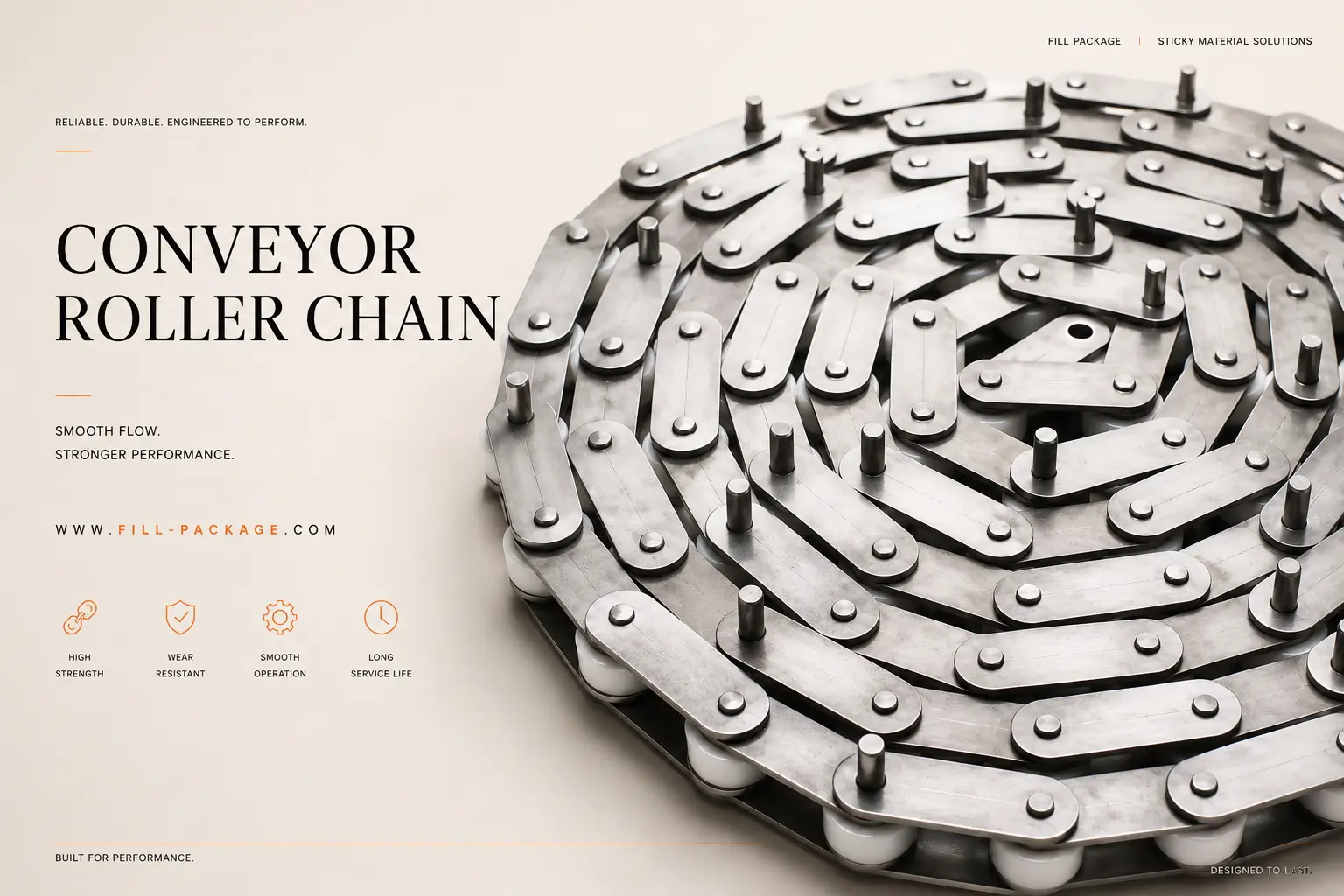
In practice, the conveyor roller chain works in continuous contact with three other components. First, carrying rollers support the chain weight on the loaded run. Second, nylon guide rails keep the chain tracking straight on the return run. Third, drive sprockets transmit motor torque to the chain. Each interface has its own friction contribution. When any one degrades, the resulting friction increase is absorbed by the chain — accelerating elongation and reducing service life.
This article explains how the four components work together and why each interface matters. It also shows how understanding the system prevents premature chain failures that appear to be quality problems but are, in fact, friction management failures.
For chain specifications: C2052 Conveyor Roller Chain. For sprocket specifications: Bucket Elevator Sprockets.
Section 1 — The Four Contact Interfaces
The Four Friction Interfaces in a Z-Type Bucket Elevator
In a Z-type bucket elevator, the chain runs a continuous loop from the bottom boot sprocket to the top head sprocket and back. Along this path, the chain contacts four different components. At each point, friction is either managed correctly — or it becomes a load the drive motor and chain must absorb.
| Contact Interface | Localização | Função | Friction Contribution if Degraded |
|---|---|---|---|
| Chain roller on carrying roller | Loaded (upward) run | Carrying rollers rotate under the chain, converting sliding friction to rolling friction. Without them, the chain slides across the casing floor. | A seized roller converts rolling to sliding friction, increasing local chain tension by 3–5× and causing accelerated link plate wear. |
| Chain side plate on guide rail | Return (downward) run | Nylon guide rails keep the chain laterally aligned, preventing it from contacting the casing walls. | A worn rail with a groove deeper than 3mm generates friction on every chain pass, increasing return-run tension and accelerating side plate wear. |
| Chain roller on drive sprocket | Top and bottom sprockets | Sprocket teeth engage chain rollers to transmit torque and maintain tension. This is the highest-load interface in the system. | Shark-fin tooth wear changes engagement geometry, increasing tension variation and creating impact loads that accelerate elongation. |
| Chain inner plate on bushing | Internal to every chain link | The bushing rotates around the pin as the chain bends over the sprocket. This is the primary wear interface that causes elongation. | Insufficient lubrication accelerates pin-bushing wear. In food environments, lubrication is washed away daily and must be reapplied regularly. |
The system insight: Chain elongation is the measured result of cumulative friction load across all four interfaces. A chain that elongates faster than expected is not necessarily a quality failure. Instead, it is frequently a symptom of a degraded component elsewhere in the system. Therefore, always inspect all four interfaces when a chain reaches its replacement threshold.
Section 2 — Carrying Rollers
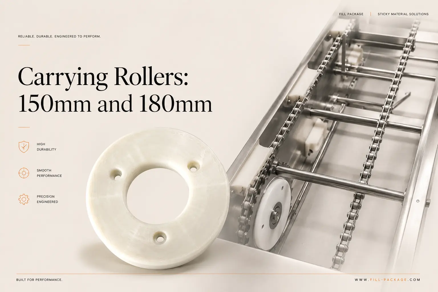
Carrying Rollers: 150mm and 180mm
Carrying rollers are positioned along the elevator casing at regular intervals on the loaded run. Their function is straightforward: they rotate as the chain passes over them, transforming sliding contact into rolling contact. As a result, the friction force the drive motor must overcome drops by approximately 70–80% compared to a chain dragging directly on the casing floor.
150mm vs 180mm: Selecting the Correct Size
Two standard carrying roller diameters are used in Z-type elevator systems. The correct size depends on the elevator frame width and chain specification:
| Roller Size | Aplicativo | Chain Compatibility | Replacement Indicator |
|---|---|---|---|
| 150 mm | Standard Z-type elevators — the most common size for 1.8L and 4L bucket systems. | C2042 and C2052 double-pitch chain. | Visible flat spot on the roller surface. Roller does not spin freely when pressed by hand. |
| 180 mm | Wide-frame Z-type elevators — used with 6L bucket systems and heavy-duty configurations. | C2062 and C2082 heavy-duty chain. | Same as above. Additionally, listen for a grinding sound during operation. |
Why Seized Carrying Rollers Cause Chain Failure
A carrying roller that stops rotating creates a fixed friction point on the loaded run. The chain link plate then slides across the stationary roller surface. This generates heat and wears a groove into both surfaces. Over time, the groove concentrates stress at the link plate hole. Eventually, a fatigue crack initiates — and the plate fractures.
Consequently, a chain failure that looks like a random link plate fracture is often traceable to a seized roller at that exact position. Replacing the chain without also replacing the seized roller will cause the new chain to fail at the same location within months.
Section 3 — Nylon Guide Rails
Nylon Guide Rails: Lateral Tracking on the Return Run
On the return run, the empty chain and buckets travel back down to the boot under gravity. Without a lateral constraint, the chain would wander across the casing width, contact the walls, and generate friction and noise. Guide rails, running along the inside of the casing on each side of the chain path, prevent this.
Why Nylon — Not Steel
Nylon guide rails are specified for three reasons, each directly relevant to chain service life.
First, nylon has a lower friction coefficient than steel. The chain side plate slides against nylon with much less resistance than it would against steel. Second, nylon is self-lubricating. The PA matrix retains a thin surface film that further reduces friction at the contact point. Third, nylon is softer than the chain side plate material. As a result, wear occurs preferentially on the nylon rail — making the rail the sacrificial component and extending chain service life.
In practice, a correctly specified nylon guide rail extends chain side plate service life by approximately 20–30% compared to a steel rail under the same conditions.
Square vs Arc Profile Guide Rails
Two guide rail profiles are available for Z-type elevator installations.
The square section guide rail is used on the straight vertical sections of the casing. The arc profile guide rail is used at the curved transition sections — at the top and bottom of the elevator where the chain changes direction. At these curves, the guide rail must follow the chain path geometry.
In most Z-type installations, the square section rail is the primary specification. Arc profile rails are required at transitions and are typically supplied as part of the casing assembly. When ordering replacement guide rails, therefore, confirm whether square or arc profile is required for your specific casing position.
Section 4 — Custom Chain Plates
Custom Chain Plates: Extending the System Beyond Bucket Conveying
For applications where the elevator chain must also serve as a conveying surface, standard chain links can be upgraded with custom chain plates. These add baffles, cleats, or sidewalls to the chain surface. In turn, the chain becomes a full conveying system for bulk materials that cannot be conveyed in buckets.
The detailed specification parameters for custom chain plates are covered in the third article in this series. Nevertheless, it is worth noting here that chain plates add weight and aerodynamic drag to the chain assembly. Both factors increase the drive load. As a result, always confirm the additional chain weight with the elevator supplier before upgrading to custom chain plates on an existing elevator.
→ Custom Chain Plates: How to Specify Baffle Height and Effective Width
Section 5 — System Maintenance Logic
The Correct Maintenance Sequence for the Complete Drive System
Because chain elongation results from all four friction interfaces, the correct maintenance approach addresses all four simultaneously — not just the chain. The sequence below ensures that replacing one component does not cause premature failure of the new component due to a degraded partner.
| Maintenance Event | Chain | Carrying Rollers | Guide Rails | Rodas dentadas |
|---|---|---|---|---|
| Annual scheduled maintenance | Measure elongation. Replace if >2%. | Spin each roller by hand. Replace any that do not spin freely. | Check groove depth. Replace if >3mm. | Inspect tooth profile. Replace if shark-fin wear on 3+ teeth. |
| Chain replacement (elongation) | Replace full chain length. | Replace all seized rollers — do not fit new chain over seized rollers. | Inspect and replace worn rails. | Replace sprockets if shark-fin wear present. Always replace sprocket with new chain. |
| Sprocket replacement (tooth wear) | Inspect elongation. If >1.5%, replace chain at the same time. | Inspect rollers. | Inspect rails. | Replace both drive and driven sprockets together. |
| Unplanned stop (chain jump) | Full inspection — check for fracture and elongation. | Identify and replace the seized roller that caused the local tension spike. | Inspect for damage at the jump location. | Full tooth profile inspection — shock load may have damaged teeth. |
Conclusão
The Chain Is the Indicator — the System Is the Cause
A Z-type bucket elevator chain that elongates faster than expected is signalling a problem in the friction management system — not just in itself. By maintaining all four contact interfaces together (carrying rollers, guide rails, sprockets, and the chain’s own pin-bushing interface), the service life of the complete drive system is significantly longer than can be achieved by replacing the chain alone.
Furthermore, the custom chain plate capability extends the system beyond bucket conveying. It opens a wider range of material handling applications — with the same dimensional confirmation process that applies to all other components in the range.
Get a complete elevator parts quote. Send your elevator model, chain pitch, and bucket configuration. We provide a quotation covering chain, sprockets, carrying rollers, guide rails, and buckets — all confirmed compatible — within 24 hours. Contate nossa equipe técnica
Continue lendo: The Synergetic Connection Between Rollers, Tracks, and Sprockets →
FAQ — Elevator Drive System Components
Q: How often should carrying rollers be replaced?
Inspect carrying rollers at every scheduled maintenance interval (every 3–6 months). Replace them whenever they fail the spin-freely test. In food factory environments with daily washdown, bearing life is typically 18–36 months under two-shift operation. However, a single seized roller can cause chain failure within weeks. Therefore, spin-testing matters more than a fixed interval. Replace immediately on failure — do not wait for the next scheduled date.
Q: What is the correct guide rail groove depth for replacement?
Replace nylon guide rails when the groove reaches 3mm depth. Beyond this point, the chain runs in a channel rather than against a flat surface. This creates additional lateral constraint and friction. At 5mm depth, the side plate begins to contact the substrate beneath the nylon, causing metal-on-metal wear. Monthly inspection with a depth gauge or feeler gauge is sufficient to track groove progression.
Q: Can I use the same carrying rollers and guide rails with a different chain pitch?
Carrying rollers are not chain-pitch-specific — the 150mm and 180mm sizes are compatible with all standard ANSI double-pitch chain widths. Guide rails, however, must match the elevator casing track width, which is fixed at the elevator design stage and is independent of chain pitch. When changing chain pitch (for example, upgrading from C2052 to C2062 for higher load), confirm that the casing and sprocket are also being upgraded. A pitch change that is not reflected in the sprocket specification will cause immediate tooth