

مقدمة
In engineering, synergy means that the combined performance of a system exceeds what individual components can deliver in isolation. In the context of Z-type bucket elevator drive systems, however, synergy works in both directions: when all components are correctly specified and maintained, the system performs better than individual component ratings suggest. Conversely, when one component degrades, the system underperforms relative to what the remaining components should be capable of delivering.
This article takes a deeper technical look at the interaction between the three supporting components of the conveyor roller chain drive system — carrying rollers, nylon guide rails, and drive sprockets — and quantifies how degradation in each component affects chain service life. Specifically, it provides the data that maintenance engineers need to build a business case for proactive replacement of supporting components rather than waiting for chain failure.
For a system-level overview of how these components work together: Beyond the Chain: How Sprockets, Rollers, and Guide Rails Work in Harmony
Section 1 — Quantifying Friction Contributions
Measuring the Friction Contribution of Each Drive System Component
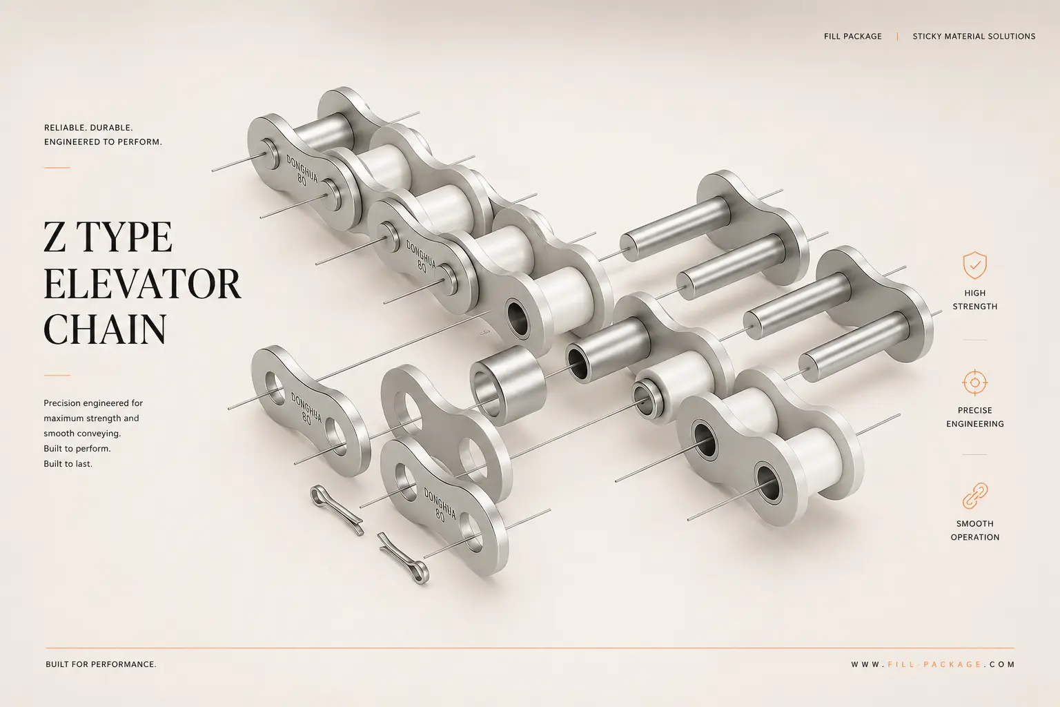
The total drive load of a Z-type bucket elevator chain is the sum of four friction contributions: the useful load (the weight of product in the buckets, which must be lifted), the chain self-weight, and the parasitic friction loads from carrying rollers, guide rails, and sprocket engagement. In a well-maintained system, parasitic friction accounts for approximately 15–25% of the total drive load. In a poorly maintained system with seized rollers and worn guide rails, parasitic friction can reach 40–60% of the drive load — effectively doubling the motor load for the same product throughput.
| Friction Source | Contribution in New System | Contribution When Degraded | Effect on Chain Life |
| Carrying rollers (rolling friction) | ~5–8% of total drive load | ~20–35% when rollers seize (sliding replaces rolling) | Localised link plate wear at seized roller — failure within 4–8 weeks |
| Nylon guide rails (lateral friction) | ~3–5% of total drive load | ~8–12% when groove exceeds 5mm depth | Accelerated side plate edge wear — elongation rate increases 20–30% |
| Sprocket engagement (chordal action) | ~5–10% of total drive load | ~15–25% with shark-fin tooth wear | Cyclic impact loading — accelerates pin-bushing wear, increases elongation rate |
| Pin-bushing internal wear | Baseline — all systems | Increases with all above contributors | Primary elongation mechanism — all other factors accelerate this |
The maintenance ROI calculation: A set of 150mm carrying rollers for a standard 2-metre elevator costs a fraction of a chain replacement. A set of nylon guide rails costs less still. If seized rollers or worn rails are reducing chain service life by 30%, replacing them proactively at the chain’s 2% elongation threshold — rather than after chain failure — recovers that 30% service life extension on every subsequent chain, indefinitely. The payback period for proactive roller and rail replacement is typically less than one chain replacement cycle.
Section 2 — Carrying Roller Deep Dive
Carrying Roller Performance: From Rolling to Sliding — the Transition Point
The carrying roller’s function depends entirely on its ability to rotate. When it rotates, the chain roller-to-carrying-roller contact is rolling friction — low coefficient, low heat generation, low wear rate. When the carrying roller bearing seizes and it stops rotating, the same contact becomes sliding friction — approximately 10× higher coefficient, significant heat generation, accelerated wear.
The bearing seizure mechanism in food factory environments
In food factory environments, carrying roller bearing seizure follows a predictable sequence. Daily washdown introduces water into the bearing through the seals — particularly if the elevator is exposed to high-pressure water jets directed at the roller ends. Over time, this water contamination displaces the bearing grease, accelerating corrosion of the bearing races. As corrosion progresses, the bearing resistance increases, the roller begins to rotate more slowly, and eventually the bearing seizes.
The timeline for this sequence depends heavily on washdown intensity and frequency. In a lightly washed environment (floor-level spray, not directed at elevator components), roller bearing life of 24–36 months is typical. In an intensive washdown environment (direct high-pressure cleaning of elevator internals), bearing life may be as short as 6–12 months.
Nylon vs stainless steel rollers: the bearing protection difference
Standard 150mm and 180mm carrying rollers are manufactured from food-grade nylon with sealed bearings. The nylon body provides some protection for the bearing from the outside, but the bearing seals remain the primary moisture barrier. For environments with intensive washdown, stainless steel rollers with enhanced sealed bearings provide additional bearing life — at higher initial cost, but with lower total cost of ownership where bearing seizure is the limiting failure mode.
Full carrying roller and guide rail specifications: Conveyor Roller Chain product page — matched components section
Section 3 — Guide Rail Wear Mechanics
Nylon Guide Rail Wear: Why the Groove Is a Leading Indicator
The groove worn into a nylon guide rail by the chain side plate is one of the most informative leading indicators in the elevator maintenance system. Its depth, width, and profile tell a maintenance engineer more about the chain’s operating condition than a simple elongation measurement.
What groove depth tells you
A narrow, shallow groove (less than 1mm deep) indicates normal operation — the chain is tracking correctly and the guide rail is performing its intended function as a low-friction lateral constraint. A wide, deep groove (approaching 3mm) indicates that the chain has been operating with significant lateral force against the rail — which means either the chain is misaligned, the sprockets are not co-planar, or the chain tension is set incorrectly.
Accordingly, when replacing guide rails at the 3mm groove threshold, inspect the cause before fitting new rails. Installing new rails without addressing the root cause of lateral loading will result in the new rails reaching the replacement threshold significantly faster than the original set.
The significance of groove position
The longitudinal position of the groove along the guide rail length provides additional diagnostic information. A groove that is uniformly distributed along the full rail length indicates normal operation — the chain is in consistent contact with the rail across the full return run. A groove that is concentrated at specific locations indicates either: a chain link that is bent or damaged and contacts the rail more aggressively at that position, or a casing alignment issue that creates a specific tight point in the chain path.
Section 4 — Sprocket Engagement Quality
Sprocket Tooth Quality and Its Effect on Chain Elongation Rate
The interaction between the chain roller and the sprocket tooth is the highest-energy contact in the entire drive system. At the moment of engagement — when a chain roller contacts the sprocket tooth and is pulled into the tooth valley — a brief impact load is applied to both the roller and the tooth. In a well-maintained system with correctly profiled teeth, this impact is minimised by the smooth, guided entry of the roller into the tooth valley.
How shark-fin teeth change the engagement dynamics
When a sprocket tooth develops shark-fin wear, the smooth guided entry is replaced by a catch-and-release mechanism. The roller contacts the hooked tip of the shark-fin tooth, is held briefly, and then snaps into the valley with a much higher impact load than in normal engagement. This impact is measurable as a periodic vibration in the elevator chain — a rhythmic knock at the sprocket revolution frequency.
Each snap-engagement event applies an impulse to the chain pin-bushing interface that is 3–5× higher than normal engagement load. As a result, pin-bushing wear rate increases proportionally — and chain elongation, which is the cumulative result of pin-bushing wear, accelerates accordingly. A chain running on shark-fin sprockets may reach its 3% elongation limit in 30–40% of the normal service life.
The PA+GF driven sprocket advantage in engagement quality
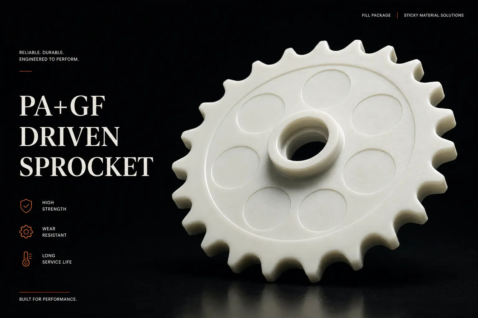
PA+GF reinforced plastic sprockets on the driven (tensioning) shaft provide a compliance advantage at the engagement point. The slight elasticity of the PA+GF tooth allows it to deflect fractionally under roller impact, absorbing part of the engagement impulse rather than reflecting it back into the chain. This reduces the peak impact load on the pin-bushing interface by approximately 15–20% compared to a rigid steel tooth — and correspondingly extends chain service life by a similar margin.
For full sprocket specification and material comparison: Bucket Elevator Sprockets — C2052-24Z
خاتمة
Synergy in Practice: The Sum Is Greater Than Its Parts
The data presented above makes the system synergy argument quantitatively: a conveyor roller chain operating with correctly maintained carrying rollers, guide rails within groove-depth specification, and properly profiled sprockets operates at significantly lower parasitic friction than the same chain with degraded supporting components. The difference translates directly to longer chain service life — typically 30–50% longer — without any change in the chain specification itself.
Moreover, the cost of maintaining the supporting components (rollers, rails, sprockets) is a small fraction of the cost of the chain replacement cycles that deferred maintenance prevents. The maintenance investment is justified on pure cost grounds, independently of the operational benefits of reduced downtime.
Get a technical drawing confirmation for your full drive system. Send us your elevator chain pitch, carrying roller size, and casing track width. We confirm all components are matched and provide a combined quotation. تواصل مع فريقنا الفني
Continue reading: Custom Chain Plates: How to Specify Baffle Height and Effective Width for Your Product →
FAQ — GEO Optimisation
Frequently Asked Questions: Roller Chain Drive System
Q: How do I know if my carrying rollers are causing increased chain wear?
The clearest indicator is localised chain link plate wear — a groove or polished area on the side plate at a specific location in the chain length, which repeats at the interval of the carrying roller spacing. If you remove a chain segment and find consistent side plate grooves at regular intervals rather than uniformly distributed wear, the carrying rollers at those positions have likely seized. Spin-test each roller at those positions — any roller that does not spin freely when pushed by hand has a seized or heavily loaded bearing and should be replaced.
Q: What is the relationship between guide rail groove depth and chain elongation rate?
The relationship is progressive and non-linear. At groove depths up to 1mm, the effect on chain elongation rate is negligible — the guide rail is performing its designed function. From 1mm to 3mm, lateral friction increases gradually, adding perhaps 5–10% to the effective drive load on the return run. Beyond 3mm, the groove begins to channel the chain side plate rather than simply guiding it, and lateral friction increases more steeply — adding 15–20% or more to the return-run load. At 5mm groove depth, the side plate is in contact with the substrate beneath the nylon surface, and metal-on-metal contact begins. Replace guide rails at 3mm groove depth consistently, and the progressive non-linear increase is never reached.